Development and progress of the permanent magnet MRI
Hitachi Medical Corporation
Hirokazu Kimura, Shigenobu Yanaka, Masao Kuroda,
Hiroshi Nishimura, Hiroyuki Takeuchi, Shigeru Sato
1. Introduction
In 1980, Hirokazu Kimura, one of the writers of this article, was transferred from Hitachi, Ltd. to Hitachi Medical Corporation (hereinafter referred to as HMC) to be involved in the business related to medical equipment, and participated, for the first time in November of that year, in the exhibition sponsored by Radiological Society of North America (RSNA), when the research and development of magnetic resonance imaging system (MRI) just began in the world. Only one manufacturer exhibited MRI, and only three MRI-related papers were presented at RSNA of that year. The rapid progress in the subsequent years in US and Europe was astonishing.
Hitachi, Ltd., the main company of Hitachi Group, had already produced, at Naka Works, Instrument Division, the nuclear magnetic resonance (NMR) system for chemical research, such as analysis of molecular structure and chemical reaction. Based on their experience, Naka Works started research and production of MRI for medical use, and delivered, in 1984, the first product of 0.15 Tesla (hereinafter T) normal conducting magnetic type to Tokyo Women's Medical University.
On the other hand, HMC had already mastered the technology for X-ray computed tomography (CT) and medical image processing. Their young engineers had a strong desire to make their own MRI by all means. In 1985, after the considerable discussion with executive managers of Hitachi, Ltd. and Naka Works, a conclusion was reached to share production. Naka Works was to produce the superconducting MRI using a high or medium magnetic field, which may become a mainstream, while HMC was to produce the normal conducting MRI using a low magnetic field.
Kimura was not interested in the normal conducting MRI of electromagnetic type, which required much electric power and cooling water, and which was heavy and large. Instead, he paid his attention to a permanent magnet MRI. In those days, FONAR, a US company, marketed a product, which used a ferrite magnet and weighed as much as 100 tons. But, reputation was not satisfactory.
The research in Japan on magnetism enjoyed globally good reputation since Dr. Hantaro Nagaoka achived a great success in this field. Dr. Kotaro Honda, Dr. Yogoro Kato and Dr. Tokushichi Mishima invented KS steel, ferrite and MK steel, respectively. These magnetic materials were easily available here, and in that sense Japanese manufactures are in an advantageous position.
Around 1955, Kimura developed an electron microscope of permanent magnet excitation type using NKS steel. This device was well received because of small size, high performance and unique features. It was exhibited at the Japanese government hall of the Brussels Exposition 1958, winning the Grand Prix. As of 1985, new magnetic materials were developed coming from neodymium, iron and boron, which were more powerful than NKS steel (of higher energy-product of about 3.5 times of NKS steel and about 8 times of a ferrite magnet). Kimura estimated, on his calculation, that if these materials were used, a 0.2T MRI would weigh less than 10 tons, which would be much lighter than it used to weigh.
The magnetic materials for our electron microscopes of permanent magnet excitation type were supplied formerly by Sumitomo Special Metals Co., Ltd. (now, NEOMAX, and hereinafter referred to as Sumitomo). They accepted willingly our request for their assistance. It encouraged the enthusiastic members of our Development Design Section, who were given a chance of long-awaited MRI development on their own. They responded to expectation, completing a development process for a short period of time of about one year and 6 months. In March 1987, a clinical test of prototype was started at Ibaraki Hitachi General Hospital, and the first clinical-use MRI was shipped in December of that year.
RSNA is the world's largest academic meeting and exhibition mainly for medical diagnostic imaging devices. It is a gateway for medical device manufactures to open up an international market. Although HMC displayed X-ray CT, an in-house product, by the OEM (Company P) brand since 1983, it did not have its own display booth. This was always very regretful. Completion of a unique, permanent magnet MRI was a good opportunity to plan overseas expansion of business. In 1989, we established Hitachi Medical Systems America, Inc. (HMSA) in US, and Hitachi Medical Systems Europe GmbH (HMSE) in Europe. At RSNA in December of that year, we opened the Hitachi booth for the first time, and displayed the permanent magnet MRI mainly and ultrasound equipment etc.
This permanent magnet MRI is featured with small size and high image quality. Its self-shield type results in the lightweight of system. Compared with the conventional type, an installation space is halved, and a running cost is reduced to one fifth or sixth. Since the beginning of sale, it enjoyed a good reputation both in the Japanese and overseas markets, increasing the market share rapidly. In subsequent years up to the present, we have made further improvements, such as higher performance, useful software, higher magnetic field, open type system and so on.
Each writer describes his assigned work in this development process as follows.

2. Development of magnetic circuit (joint development with Sumitomo.)
In order to use a permanent magnet and to put the magnetic field for MRI in practical use, it was necessary to solve many technical problems. We asked Sumitomo to fully cooperate with us. In 1983, Sumitomo produced commercially the powerful magnet (called NEOMAX) coming from neodymium, iron and boron, and then a 0.15T cylindrical magnetic circuit using this magnet. In March 1985, as the next step, they completed a 1/5-scale model of 4-pillar magnetic circuit of 0.15T.
Moreover, Mr. Tetsuo Aoyagi (afterward, President) of Sumitomo and Hirokazu Kimura (then, President) of HMC were old acquaintances, when an electron microscope of permanent magnet excitation type was developed by Kimura who worked at Hitachi Central Research Institute.
In May 1985, both companies had the first meeting at Yamazaki Works of Sumitomo to discuss the magnetic circuit for MRI using a permanent magnet. Hitachi described the clinical importance MR imaging in future, and many merits of permanent magnet system compared with normal conducting and superconducting magnet systems, while Sumitomo explained the future prospect of performance improvement of magnetic materials, and the development status of magnetic circuit for MRI. Both companies reached a cooperative agreement to jointly develop a new magnetic circuit for MRI.
Moreover, we had technical liaison meetings periodically with Sumitomo. as a technical forum to promote development. This forum became the center for technical development of magnetic circuit required for higher performance and function of MRI.
Three months passed since the first meeting in May. On July 30, the specification for prototype magnetic circuit was finalized. The magnetic field intensity is most closely related to the image quality and price, and most difficult to determine. These items are mutually dependent. When the static magnetic field intensity varies, the required volume (price) of magnet is proportional to the square of magnetic filed intensity, while the acquired image quality is proportional to the magnetic field intensity.
Although the 0.15T normal conducting equipment was mainly used in the market in those days, the image quality was not adequate. At the minimum, the image quality must be as high as that obtained by a 0.3T superconducting equipment. We took advantage of a vertical magnetic field (which gives the image quality 1.4 times higher than a horizontal magnetic field), and selected the intensity of 0.2T. This intensity was optimal as a trade-off of availability of magnetic materials of those days. Figure 1 shows the relation of intensity to other factors that were used as a basis to determine this intensity. They are signal-to-noise ratio, image contrast, and magnet volume (price).
 |
| Figure 1. Relation diagram to determine magnetic field intensity |
Patients who underwent the examination by a normal conducting MRI often felt the uneasiness when they were placed into a narrow and deep hole for acquisition of images. In order to reduce their uneasiness, the magnet was shaped with a wide opening and a short depth. This shape was also expected to be convenient for expansion of clinical application of MRI in future. This was a fundamental concept for magnetic circuits and it developed into a "patient-friendly, open MRI" in the subsequent progress of magnetic circuits.
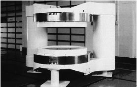
The No. 1 prototype of magnetic circuit was carried in to the Technology Institute of HMC on December 28, 1985, the year's last day of routine work. The 7-ton circuit looked compacter than we though in advance. After finalization of the specification, five months passed, in which various technical problems came up. The serious problem was nonuniform magnetic field caused by a rectangular structure. At a part of magnetic circuit, an iron plate was installed in order to control the magnetic field. Small iron plates of various sizes were placed on the pole pieces. This shimming technique successfully kept uniformity within 60 ppm in the target imaging space. Until then, it took us the first several days of the new year. At last, we completed a 0.2T permanent magnet type magnetic circuit for MR imaging. Figure 2 shows the appearance of the No. l prototype of magnetic circuit.
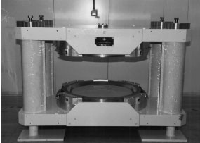 |
| Figure 2. No. 1 prototype of magnetic circuit |
3. Trend of domestic and overseas manufactures of permanent magnet MRI
FONAR in US manufactured the first commercial product of MRI. In 1980, they manufactured commercially the first whole-body MRI using a ferrite magnet with static magnetic intensity of 0.04T. Afterward, FONAR developed a 0.3T system to improve the image quality, which was as heavy as 100 tons and was not used widely.
According as powerful magnetic materials became commercially available, many manufacturers started to study the business feasibility of permanent magnet MRI. FONAR and six other companies, mainly in US, were involved in development as of April 1987.
In Japan, Company S produced commercially a 0.15T system consisting of a cylindrical magnetic circuit in November 1986, being followed by Company T and Company A. But, they have now stopped production. Afterward, Company G sells a permanent magnet MRI like ours.
On the other hand, MR imaging proved effective to diagnose limb joints. The dedicated equipment for that purpose was developed. Company E in Italy, for example, installed 800 or more sets that were exclusively intended for diagnosis of limbs.
4. The situation of early stage of development
The 1970s was defined as the early stage of X-ray CT, while we can define the 1980s as that of MRI.
In June 1985, HMC organized a project team for development of MRI. In those days, a considerable number of staff was assigned to development of X-ray CT to cope with its rapid growth of that business. Then, a new principle of reconstruction for MRI, Fourier transform, proved effective. It was different from and more efficient than the back projection technique for X-ray CT. The manufacturers in US and European countries shifted their efforts to the superconducting MRI. Also within HMC, the MRI development project recruited the respective personnel for hardware, software and application. All the enthusiastic members were convinced that the permanent magnet MRI would be able to realize such techniques for imaging and medical application that could be realized only by the superconducting MRI. They were not so desperate as to burn their bridge behind them, but enjoyed doing research under the free environment. The managers' tolerance allowed them to do what they wanted to do. I think that it led to a success.
The respective research field was assigned as follows. The magnetic circuit of permanent magnet was assigned to Shigeru Sato; electronics, to Hiroyuki Takeuchi; software, to Hiroshi Nishimura and coordination, to Masao Kuroda. The project leader was Shigenobu Yanaka, who planned the budget and liaised with Hitachi, Ltd. in order to start the project.
Happenings often occur in a development process. As mentioned above, the No. 1 prototype of magnetic circuit was carried in to a newly built shield room in the Technology Institute at the end of 1985. The circuit was lifted from a truck with a large crane and placed on the ground. It was carried in to the shield room, using a winch. After it was installed, the happening occurred. The magnetic circuit attracted suddenly the jack being carried by a workman. Although the intensity of the circuit was 0.2T, the intensity of convergent magnetic beams reached 1T at the edges of upper and lower pole pieces. When the workman approached, his jack was attracted with an explosive sound. Everyone heard the sound, observing all at once what happened, and gazing aghast for a while to dreadfulness. We used a winch to pull the jack along the surface and removed it somehow to prevent a further accident. Everyone was impressed to see the strength of attractive force of even a static magnetic field.
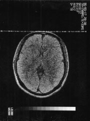
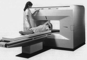
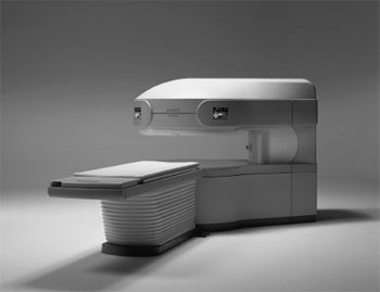
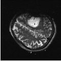
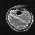
Figure 3 shows the head MRI image of a team member that was taken for the first time in March 1986 (imaging time: 12.8 minutes). Figure 4 shows the appearance of a commercial model MRP20.
 |
|
 |
| Figure 3. The first head MRI image |
|
Figure 4. Appearance of MRP20 |
The permanent magnet MRI reached the level of a commercial product. Electrical safety inspectors came from Japan Machinery Metals and Inspection Institute (JMI), now, Japan Quality Assurance Organization (JQA). They asked us with surprise, saying "The Hitachi's equipment is only this one?" We were also surprised at this question. In those days, an MRI system usually consisted of several units. They were three units for XYZ gradient magnetic field power supply, an RF power supply unit, a main power supply unit and a console. The inspectors were surprised to see that all the units except a console were housed into a single unit, and that a special machinery room was not necessary any more. Their surprise was due to our design concept. From the beginning we knew that the available space in the hospital was limited, and employed space-saving design for convenience of installation. Thus, a permanent magnet MRI was featured with compactness, space-saving design, and low running cost, resulting in much more sales amount than we expected.
At the early stage, we encountered various difficulties to expand the market of permanent magnet system. In order to increase a range of products, we developed a 0.12T low-end model. Unfortunately, we sold only twenty plus systems and discontinued production. This was because MRI with intensity of 0.2T or higher made a rapid progress when we started shipment of 0.12T system.
In addition, we delivered the first MRI-mounted vehicle, as mobile MRI, for the first time in Japan to Nakamura Memorial Hospital in Sapporo. A mobile MRI was considered most suitable to cover a wide area such as Hokkaido, but it was not so popular as it was in US. A stationary model with radiologists residing was preferred to a mobile model.
MRP20A was well received as a compact permanent magnet globally, winning several prizes. They were the R&D Top 100 World New Products Prize and the 23rd Japan Society for the Promotion of Machine Industry Prize in September 1988; G-Mark Prize in October of that year; the Nikkan Kogyo Shimbun Top 10 New Products Prize and the Nikkei Industrial Daily Excellence Prize in January 1989; and the Ministry of Health and Welfare (Distinguished Service for Health and Science) Prize in December 1990.
5. Technological innovation: Fight against eddy current and residual magnetic field
The development of a permanent magnet was always a fight against the eddy current and residual magnetic field. At the early stage of development, we installed the recommended version of pulse sequence protocol, when we shipped the system from the factory. However, if the phase encode direction was changed, images became blurred. That was the beginning of our struggle. The cause of blur was not identified at first. We made even a measuring instrument ourselves. We found out gradually that the blur was specific to a permanent magnet. We tried various kinds of materials of pole pieces in order to minimize the eddy current and residual magnetic field, which were caused by turning on and off of the gradient magnetic field. Finally, we succeeded in decreasing these sharply, producing a commercial model of MRP20EX, and presenting five technical papers at RSNA.
After this magnet was completed, it proved very effective for improvement of image quality of Fast Spin Echo (FSE) and MR Angiography (MRA), which is imaging of blood vessels. The image became very sharp for MRA Time of Flight and Phase Contrast techniques. This led to further progress to an open MRI.
Around 1990, GE announced FSE, which reduced the measurement time drastically. This was an improvement on Rapid Acquisition with Relaxation Enhancement (RARE) technique announced by Dr.Henning of Germany.
This technique irradiates repeatedly two or more 180-degree pulses, repeating the spin echo, assigning two or more measurement signals to different phase encoding, and realizing a high-speed imaging. It was epoch-making in that the imaging time decreased from about 15 minutes to 2 to 3 minutes. Immediately after the announcement, it attracted much attention, because it was seen as a promising measurement method for superconducting equipment.
As a result of investigation, we found out that the gradient magnetic field is the basis of this technique, and that the field must be more accurate at least by one digit, preferably by two digits, than the former models. Some people feared that such accuracy would be difficult to achieve by a permanent magnet system, and that the failure would end the MRI business itself. As mentioned above, however, we improved the magnetic circuit, the gradient magnetic field coil, and the measurement compensation that is peculiar to a permanent magnet. Thus, we completed FSE with our comprehensive engineering capability. Everyone was heartily relieved to see a sharp image taken only in three minutes. Where there is a will, there is a way.
6. Evolution to an open MRI
The semi-open 4-pillar magnetic circuit (Figure 2) at the early stage evolved to the 2-pillar asymmetric AIRIS, and ultimately to the 1-pillar open APERTO. The unique and fully open AIRIS was received so well in the market that it established Hitachi's reputation as a manufacturer of an open MRI. MRI requires the high homogeneity of the static magnetic field. For that purpose, two pillars should be structured symmetrically. In that sense, the asymmetric structure is disadvantageous. We repeated much heated discussion at the regular meetings with Sumitomo, finally building a homogeneous magnetic circuit even with the asymmetric structure.
Figure 5 shows the 2-pillar asymmetric magnetic circuit of a 0.3T open MRI that was put in practical use. This design was epoch-making in those days. This magnetic circuit had an opening also in a patient's transverse direction, so we named this model an open MRI. It became the origin of subsequent open MRI.
 |
| Figure 5. Asymmetric 2-pillar magnetic circuit |
As mentioned above, HMSA was in charge of sale in US. At that time, the 0.2T model sold well, and the 0.3T model was considered unnecessary. HMSA seemed to consider that there was no big difference between 0.2T and 0.3T. However, our engineers continued to improve the image quality without giving up, and happened to show the images to HMSA. As soon as they saw the images, they changed their mind, asking us successively, "Don't you have any magnets available for US market? How soon can we get them?", and demanding prompt production. They were quick to correct their initial misjudgment, making a sales strategy immediately. The resultant sales amount was much more than we expected. We thought that we were lucky to have a good business partner .
This AIRIS also won many prizes. They were G-Mark Prize in September 1995; German iF Design Prize in June 1996; Nikkan Kogyo Shimbun Machine Industry Design Prize, International Trade and Industry Minister Prize, and US Excellence Gold Prize in July of that year.
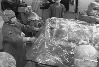
By taking advantage of the open structure and the reduced magnetic leakage, we expanded the application of MRI from interventional radiology (IVR) to intraoperative assistance (an intelligent operating room), such as intraoperative verification of total tumor resection in neurosurgery, thus contributing to increase a patient's five-year survival rate. The MRI-aided brain surgery is promising.
One-pillar MRI APERTO (0.4T) was designed to keep the leakage field as small as that of 0.3T, to converge the magnetic flux to the single pillar, and to minimize the cost increase caused by high magnetic field. Sumitomo cooperated closely with us, employing the leakage field suppression technique, which confined the leakage field within the magnetic field. The shimming coil was also mounted to realize high performance and light weight.
Figure 6 shows the appearance of the APERTO, which won Nikkan Kogyo Shimbun Machine Industry Design Prize (Screening Committee Special Prize) in January 2003.
At present, the shimming technique is mounted. We realized Echo Planar Imaging (EPI) with high-speed pulse sequence, Diffusion Weighted Imaging (DWI), Tractography to trace the nerve, and Tensor Imaging. Moreover, we improved the magnetic field uniformity and obtained the water-fat-separation image, which had been thought to be produced only by superconducting equipment.
 |
| Figure 6. Ultimate 1-pillar open MRI (APERTO) |
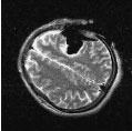
Figure 7 shows the heart and great vessels in the case of right-subclavian-artery obstruction, taken by AIRIS II Comfort (0.3T) (imaging time: 17 seconds). Figure 8 shows DWI by intraoperative MRI of this equipment.
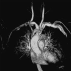 |
| Figure 7. Image of the heart and great vessels (AIRlS II Comfort) |
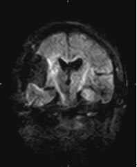 |
Figure 8. Image of intraoperative DWI (AIRlS II Comfort) |
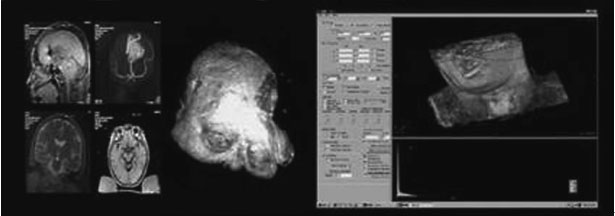
Figure 9 shows the history of development of open MRI. Figure 10 shows intratoperative MRI, image obtained, and operation navigation function such as 3-dimensional volume rendering.
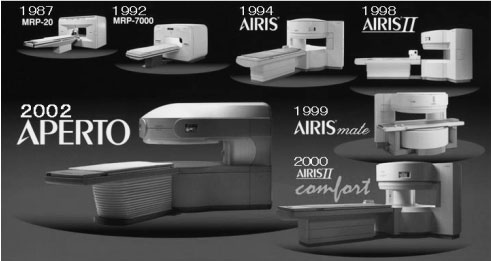 |
| Figure 9. The history of development of open MRI |
 |
|
 |
|
 |
Before operation
(after opening the skull) |
|
During operation |
|
After operation |
 |
| Intraoperative MRI |
Real-time volume rendering |
|
Figure 10. Brain surgery at an intelligent operation room using intraoperative MRI. Intraoperative images, and operation navigation image such as 3-dimensional volume rendering (Tokyo Women's Medical University)
The history of the permanent magnet MRI is described above covering the early stage of development through the present situation. This equipment is widely used in the world. As shown in Figure 11, the accumulative total installations topped 3000 at the end of December 2003, contributing to medical care in the world. We expect that it will be widely used also in Southeast Asia and China.
7. Conclusion (Development of superconducting MRl by HMC)
Hitachi Naka Works completed a superconducting MRH 500 (0.5T) in 1988, and produced MRH1500 (1.5T) in 1991. Subsequently, in December 1992, Hitachi, Ltd. transferred the superconducting MRI business to HMC.
 |
|
 |
| Figure 11. Transition of the number of Hitachi permanent magnet system MRI delivery |
As a result, HMC takes charge of the entire MRI business of Hitachi Group, including superconducting equipment. In the field of tunnel type superconducting MRI, it is not easy for us to have the differentiating technology to compete with the three big companies in the world. However, we completed a 0.7T open MRI Altaire in 2000. It is selling well in US, and 200 or more systems are in operation.
Finally, my hearty thanks goes to Mr. Tetsuo Aoyagi, Mr. Hironobu Miyamoto, and others of Sumitomo (now, NEOMAX) for their guidance and cooperation.
About the writers, all of whom belonged to HMC as of April 2004.
 |
 |
 |
|
 |
Hirokazu Kimura,
former President and Chairman |
|
Shigenobu Yanaka,
former Senior Executive Managing Director |
|
Masao Kuroda,
Executive Managing Director |
| |
|
|
|
|
 |
|
 |
|
 |
Hiroshi Nishimura,
Senior Chief Engineer,
Research & Development Center |
|
Hiroyuki Takeuchi,
Senior Chief Engineer,
MRI System Division |
|
Shigeru Sato,
Manager, MRI System Division |
Editor's postscript
 |
| Sumio Makino |
This installment of series "Development of Japanese Radiological Equipment in the Post-World War II Period" describes "Development and progress of the permanent magnet MRI" contributed by the writers of HMC. This article demonstrates the technical development capability of the Japanese people.
Our seniors rose in the postwar entire privation age. First, they developed the diagnostic X-ray equipment by industry-university cooperation. The equipment was a product of Japanese engineering ingenuity and was used to diagnose tuberculosis, which was the so-called national affliction. Next, they developed X-ray television also with Japanese engineering ingenuity, which contributed much to diagnosis and therapy of stomach cancer. This equipment was intended for clinical application of double contrast technique that was very effective for early detection of stomach cancer. Its mortality rate was notoriously higher in Japan than in other countries. Thanks to X-ray television, the mortality rate decreased sharply in subsequent years.
These achievements are all based on our national technology for development of medical and imaging devices, contributing to the health and welfare of the people. We are living a peaceful life with the longest life expectancy in the world. The members of Japan Industries Association of Radiological Systems are proud of these achievements.
In the 1970s, the computers were applied for image processing, and X-ray computed tomography was invented. Diagnostic ultrasound equipment was also introduced. In the 1980s, the age of MRI dawned and continues to this century. Recently, positron emission tomography (PET) is ready for clinical application, opening a new era of innovation.
We hope that those concerned will continue development efforts of new technologies and new medical devices, which contribute to the health and welfare of human being, thus accumulating further achievements to the history of progress.
I intend to continue this series by expanding the scope also to the related items and accessories, and to the history of our predecessors who made efforts for technical development in that field. (written by Sumio Makino in May 2004)
|